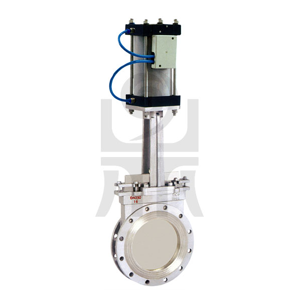
Pneumatic Knife Gate Valve

Pneumatic Knife Gate Valve
Product Model: PZ673H
Diameter: DN50 ~ 800mm
Features: Explosion, Switches, Locator
Smooth Channel, Small size, light weight, easy disassembly
Quality, skilled, global quality, to replace imported
knife-shaped incision, cut strong, self-cleaning function for fiber particles in the fluid
Slim Design, lightweight appearance, compact structure, while the flow passage port
Contact purchase
shared:
| Specifications | |||
| Design Basis | GB Standard | ANSI Standard | |
| Design Standards | GB / 12237 | ANSI B16.34 | |
| Structure Length | Folder Connection | GB / 12221 | ANSI B16.10 |
| Connection Flange Size | GB / 9113, JB / T79 | ANSI B16.5 | |
| Experiment and Test | JB / T9092 | API 598 | |
Note: The series of ball valve structure length and connection size can be designed according to customer requirements
| Technical Parameters | |
| Nominal Diameter | DN50 ~ 800mm |
| Connection Method | Wafer Type, Lug Type |
| Cylinder Form | Double Acting |
| Control Method | Switch Type, Adjustable Type |
| Nominal Pressure | 10,16bar (please specify when ordering for higher pressure) |
| Air Pressure | Double acting: 4 ~ 8bar, single acting: 5 ~ 8bar |
| Medium Temperature | W1: -40 to 180 W2: -40 to 180 W3: -30 to 425 W4: -40 to 425 |
| Ambient Temperature | Standard: -20 ~ 80 ℃ |
| Body Naterial | Carbon Steel (C), Stainless Steel (P4, P6) |
| Sealing Material | Polytetrafluoroethylene (F), Para-polystyrene (PPL), Metal hard seal (H), Cemented Carbide (Y) |
Note: other special sealing material or special temperature can also be selected according to customer requirements selection

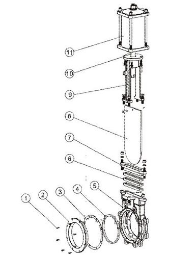
| Main Parts of the material table | ||||
| Serial Number | Part Name | Material | ||
| C | P4 | P6 | ||
| 1 | Hexagon socket screws | 1Cr18Ni9Ti | 1Cr18Ni9Ti | 1Cr18Ni12Mo2Ti |
| 2 | Cap | WCB | 1Cr18Ni9Ti | ZG1Cr18Ni12Mo2Ti |
| 3 | Gasket | PTFE | PTFE | PTFE |
| 4 | Seat | 1Cr18Ni9Ti or PTFE | 1Cr18Ni9Ti or PTFE | 1Cr18Ni12Mo2Ti or PTFE |
| 5 | Body | WCB | ZG1Cr18Ni9Ti | ZG1Cr18Ni12Mo2Ti |
| 6 | Sealed packing | Dingqing Rubber or PTFE | Dingqing rubber or PTFE | Dingqing rubber or PTFE |
| 7 | Gland | WCB | ZG1Cr18Ni9Ti | ZG1Cr18Ni12Mo2Ti |
| 8 | Gate | 1Cr18Ni9Ti | 1Cr18Ni9Ti | 1Cr18Ni12Mo2Ti |
| 9 | Stent | WCB | ZG1Cr18Ni9Ti | ZG1Cr18Ni12Mo2Ti |
| 10 | Push Rods | 45 # Steel Chrome Plated | 45 # Steel Chrome Plated | 45 # steel chrome plated |
| 11 | Pneumatic Actuators | - | - | - |
Note: The main parts and seals of the material can also be based on actual conditions or customer requirements design selection

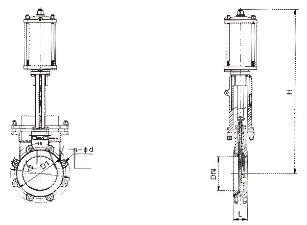
| Main Dimensions -PN16 (16bar) | |||||||||||
| Nominal Diameter [DN] | GB standard shape and connection size (PN1.0bar) | Nominal Diameter [DN] | ANSI standard form factor and connection dimensions (Class150) | ||||||||
| L | H | D | D1 | n-φd | L | H | D | D1 | n-φd | ||
| 50 | 48 | 460 | 165 | 125 | 4-M16 | 50 | 48 | 460 | 152 | 120 | 4-M5 / 8-11 |
| 65 | 48 | 520 | 185 | 145 | 4-M16 | 65 | 48 | 520 | 178 | 139.5 | 4-M5 / 8-11 |
| 80 | 51 | 570 | 200 | 160 | 8-M16 | 80 | 51 | 570 | 190.5 | 152.5 | 4-M5 / 8-11 |
| 100 | 51 | 680 | 220 | 180 | 8-M16 | 100 | 51 | 680 | 220.5 | 190.5 | 8-M5 / 8-11 |
| 125 | 57 | 780 | 250 | 210 | 8-M16 | 125 | 57 | 780 | 254 | 216 | 8-M3 / 4-10 |
| 150 | 57 | 850 | 285 | 240 | 8-M20 | 150 | 57 | 850 | 279 | 241.5 | 8-M3 / 4-10 |
| 200 | 70 | 980 | 340 | 295 | 8-M20 | 200 | 70 | 980 | 343 | 298.5 | 8-M3 / 4-10 |
| 250 | 70 | 1140 | 395 | 350 | 12-M20 | 250 | 70 | 1140 | 406 | 362 | 12-M7 / 8-9 |
| 300 | 76 | 1360 | 445 | 400 | 12-M20 | 300 | 76 | 1360 | 483 | 432 | 12-M7 / 8-9 |
| 350 | 76 | 1460 | 505 | 460 | 16-M20 | 350 | 76 | 1460 | 533 | 476 | 12-M1-8 |
| 400 | 89 | 1630 | 565 | 515 | 16-M24 | 400 | 89 | 1630 | 597 | 539.5 | 16-M1-8 |
| 450 | 89 | 1770 | 615 | 565 | 20-M24 | 450 | 89 | 1770 | 635 | 578 | 16-M118 / -7 |
| 500 | 114 | 1960 | 670 | 620 | 20-M24 | 500 | 114 | 1960 | 699 | 635 | 20-M118 / -7 |
| 600 | 114 | 2245 | 780 | 725 | 20-M27 | 600 | 114 | 2245 | 813 | 749.5 | 20-M11 / 4-7 |
| 700 | 127 | 2600 | 895 | 840 | 24-M27 | 700 | 144 | 2120 | 984 | 914.5 | 28-M11 / 4-7 |
| 800 | 127 | 2910 | 1015 | 950 | 24-M30 | 800 | 203 (127) | 2500 | 1168 | 1086 | 32-M11 / 2-6 |
| 900 | 203 (127) | 3200 | 1115 | 1050 | 28-M30 | 900 | 216 (149) | 2800 | 1346 | 1257.5 | 36-M11 / 2-6 |
| 1000 | 216 (149) | 3550 | 1230 | 1160 | 28-M33 | 1000 | 254 (156) | 3300 | 1511 | 1422.5 | 44-M11 / 2-6 |
| 1200 | 254 (156) | 4250 | 1455 | 1380 | 32-M36 | 1200 | |||||
Note: Depending on the valve torque, the different air pressure, and the different operating conditions, the matching dimensions of the actuator are also changed
| Accessories Selection | |
| The Electromagnetic Valve | Double role selection of two five-way, single-effect two-way five-way, single-control double electric control when ordering |
| Air Handling Triplets | The gas source for regulation, filtration, cylinder lubrication |
| Limit Switch | Remote feedback switch signal |
| Gymnastics | Can be achieved manually open, close the valve |
| Locator | Enter the analog signal (4-20mA or 0-10V) to adjust the valve opening |
| Remarks | The above accessories are not standard accessories, if you need to specify the order when ordering, solenoid valve and limit switch is divided into explosion-proof and not explosion-proof, for explosion-proof but also indicate explosion-proof grade |
Previous:
API Pneumatic Gate Valve
Next:
Penetrating Flap Valve


 Zhejiang public security reserve No. 33032402001552


